Carbide Base Audio Isolation Feet

Carbide Base Audio Isolation Feet

Vibrations induced from loudspeakers can turn the surfaces of a room into unwanted delayed sound radiating sources. Vibrations can also induce noise in the output of sensitive electronics such as turntables.


The patent pending design of our Carbide Base audio isolation feet control and isolate these vibrations in all directions when placed under your audio electronics and loudspeakers.

Multi-Axis Audio Isolation Feet

Separate upper and lower portions are designed to optimize vibration isolation and dissipation in vertical and horizontal directions.


The upper portion utilizes an aluminum housing machined to accept a specially formulated viscoelastic member called ViscoRing™. The ViscoRing™ acts as a damped spring supporting the equipment while isolating it from vertically oriented vibrations. It is replaceable depending on the intended supporting weight range.


A new austenitic (non-magnetic) stainless steel section resides in the top center of the upper portion to improve coupling with the underside of equipment.


The lower portion incorporates zirconia ball bearings and viscoelastic elements to enhance horizontal isolation and damping. The large bearings roll on flat raceways formed from polished hardened steel to minimize rolling resistance. The bottom is threaded to facilitate nearly 3/4″ (20 mm) of height adjustment. It can also optionally accept the 3 provided spikes to pierce through carpet.

Progressive Shape Factor

When it comes to viscoelastic materials providing isolation, more is not necessarily better. It is the low ratio of surface area supporting weight to the surface area free to bulge outward which is important for improving isolation performance. The term for this ratio is Shape Factor. The lower the Shape Factor, the greater the potential degree of isolation.


Carbide Base audio isolation feet implement viscoelastic materials with Shape Factors far lower than previous designs. The large tubular shape of the ViscoRing™ maximizes the surface area that is free to bulge. This yields a Shape Factor around half of the lower limit traditionally used for elastomeric isolators. The low shape factor is made possible by the patent pending design of the Carbide Base footer. Ridges within the upper portion progressively brace the ViscoRing™ as it compresses to stabilize it while leaving a substantial surface area free to bulge.

Universal Stud System

Carbide Base footers can be optionally mounted to equipment and loudspeakers with the supplied screws in metric thread sizes M4, M6, M8, M10 and imperial sizes #8-32, 1/4″-20, 3/8″-16, 1/2″-13. The screws are standard flat head machine screws allowing easy substitution for a different thread size or length. A removable nylon insert is provided for smaller diameter screws. A machined stainless steel jam bolt is provided to thread in behind the screw to secure it in place. The top of the jam bolt has a threaded hole to optionally accept one of the included spikes to point upwards for maximum coupling to the supported equipment.

ViscoRings™

All Carbide Base footers are the same size. Each is optimized for the weight of your equipment by choosing among the 5 available interchangeable ViscoRings™. The recommended supporting weight range with each ViscoRing™ installed is shown below.


While some isolation devices require different versions for different weights, a single version of the Carbide Base footer can support a wide range of equipment weights by simply replacing the installed ViscoRing™.

Transmissibility

Conventional floor spikes under loudspeakers transmit a significant amount of vibration energy into the floor throughout the bass and midrange frequencies. Many traditional vibration isolation devices will provide isolation at higher frequencies but exhibit an amplification of vibrations in the lower frequencies near the resonance frequency of the device.


The Carbide Base footer is unique among audio footers in its ability to effectively both isolate and damp the lowest audible frequencies. Low frequencies are important to isolate as they travel with little impedance throughout the room and equipment, degrading audio fidelity along the way. The reduction of these structure-borne vibrations improves midrange clarity and bass extension by reducing the masking effect brought on by room structure noise. This reduction in noise transmission provides equally important improvements in the high frequencies.

Spikes
Carbide Base Footers

Horizontal vibration energy transmitted from a 2-way loudspeaker into a 13.6 kg (30 lbs.) weighted aluminum plate placed on top of the loudspeaker. Measurements were taken with the plate on 4 floor spikes and then with the plate on 4 of the Evo version of the Carbide Base footers. Super Light ViscoRings™ were used. Horizontal acceleration was measured with a ACH-01 sensor, 10 dB gain, using 30 Hz to 10 kHz log swept sine excitation.

Loss Factor

Loss factor, or tangent delta, is a measure of how much vibration energy is dissipated through a conversion to heat due to the phenomenon of hysteresis. A loss factor of 0 indicates a perfectly elastic material where the oscillating force of a vibration occurs in-phase (at the same time) with the accompanying deformation of the material. A loss factor of 1 indicates a perfectly viscous material where the force and deformation are exactly 90 degrees out of phase resulting in total dissipation of vibration energy to heat.


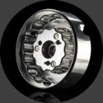
The viscoelastic materials utilized in Carbide Base footers are engineered to have an exceptionally high loss factor over a wide frequency range. The green ViscoRing™ has the highest loss factor, followed closely by the other ViscoRings™ which can support incrementally higher weights.

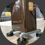
The vibration dissipation ability of a Carbide Base footer is significant enough to measurably subdue resonances in equipment being supported. The graphs below show low frequency vibrations in the panels of a test loudspeaker enclosure as measured using a calibrated accelerometer. Dips and spikes in panel acceleration indicating resonances are effectively damped when the same measurement is taken with Carbide Base footers placed under the loudspeaker.

Loudspeaker Bottom Panel Vibration
Loudspeaker Upper Side Panel Vibration

Loudspeaker panel acceleration measured with a ACH-01 sensor, 10 dB gain, using 35 to 150 Hz log swept sine excitation. The measurements on Carbide Base footers are shown in blue. The measurements on floor spikes directly on the concrete floor are shown in red. See the Vibration Dissipation Measurements for details.

Dimensions

Instructions

Changing ViscoRings™

Instructions for the removal and installation a ViscoRing™ inside the Carbide Base footer.

1 Insert supplied screwdriver down into each of the 3 top holes and unscrew the bolts housed within. Note: Once fully unscrewed the bolts will remain under the stainless steel top.

2 Pry apart the upper and lower portions to access the installed ViscoRing™. Be patient prying apart as the ViscoRing™ can become tacky and slow to separate. The bottom portion can be partially unthreaded to increase prying leverage.


3 Replace the ViscoRing™. Ensure that the new ViscoRing™ is fully seated into the recess on top of the base before placing the upper portion on top of it.

4 Align the top holes on the upper portion with the thread holes on top of the lower portion. Press the upper portion down over the top of the lower portion.


5 Insert the screwdriver into the top holes and tighten the bolts housed within. Pressing down and lightly twisting the upper portion can help guide the bolts into their holes. If the bolts still do not align with their holes, remove the upper portion and try again.

6 (Optional) Unthread the bottom section as needed to increase the height of the Carbide Base footer to level uneven loads.

Installing Bolts for Speakers

Instructions for installing bolts into the Carbide Base footer. This allows the Carbide Base footer to screw into speakers and equipment in place of spikes or stock footers.


Note: This mounting method is optional. Similar performance is possible by simply placing the tip of a speaker spike down into the hole on the top center of the footer.

1 Insert supplied screwdriver down into each of the 3 top holes and unscrew the bolts housed within. Note: Once fully unscrewed the bolts will remain under the stainless steel top.

2 Pry apart the upper and lower portions to access the underside of the upper housing. Be patient prying apart as the ViscoRing™ can become tacky and slow to separate. The bottom portion can be partially unthreaded to increase prying leverage.


3 Insert the supplied screwdriver into the slot in the bolt retainer threaded into the bottom center of the housing.

4 Unscrew the bolt retainer and set aside. Determine which bolt to use by hand screwing into the open hole on the bottom of your audio equipment or speaker. Note: The bolts provided are ANSI B18.6.3 standard flat head machine screws. If another thread size or length is required they can be purchased separately from most bolt hardware stores.


5 (Optional) If the bolt is too large for the opening in the black nylon washer, remove it by pushing down on it from the top side. For smaller bolts sized M4, M6, #8-32, or 1/4"-20 leave the nylon washer in place. The nylon washer can be pressed back into place if needed.

6 Insert the desired screw up into the bottom of the housing. While holding the bolt in place from the top of the footer, tightly screw the bolt retainer in behind it. Ensure that the bolt is protruding straight out of the top of the footer and that it does not twist in place. Note: If the bolt ever becomes loose, completely unscrew and remove the bottom of the footer. Retighten the bolt retainer by passing the screwdriver up through the bottom center hole.

7 Align the top holes on the upper portion with the thread holes on top of the lower portion. Press the upper portion down over the top of the lower portion. Insert the screwdriver into the top holes and tighten the bolts housed within. Pressing down and lightly twisting the upper portion can help guide the bolts into their holes. If the bolts still do not align with their holes, remove the upper portion and try again.

8 Screw the Carbide Base footer into the holes on the bottom of the equipment by twisting the housing.

Using Carbide Base Footers on Small Shelves

Instructions for using Carbide Base footers on small shelves. For example, the top of a bookshelf speaker stand. Removing the bottoms of the Carbide Base footers and allowing them to hang over the sides of the shelf reduces the shelf space required by the footer.


Note: This method eliminates the ability to adjust the height of the Carbide Base footers.

1 Completely unscrew and remove the bottom portion of the Carbide Base footer.

2 Place the footer so that the inner bottom center is on the shelf and allow the sides to hang off. Note: The perimeter of the inner bottom center is intentionally a sharp edge to maximize coupling with the support surface. It is not recommended for use directly on hardwood floors.


Minimum Shelf Width: 20.3 cm (8 in)   Minimum Equipment Width: 12.7 cm (5 in)

FAQ

– What separates Carbide Base footers from the competition?

We believe there are 3 primary advantages of Carbide Base footers over the competition:

  1. Low resonance frequency in all directions – An exceptionally wide bandwidth of vibration isolation means that nearly all of the audible frequency range is isolated. This includes the lowest frequencies most likely to excite room surfaces. Many devices provide limited isolation bandwidth or are effective only in certain directions.
  2. High loss factor – Specially formulated viscoelastic materials convert up to 65% of vibration energy into heat to effectively damp resonances. Vibration dissipation is higher than many other devices utilizing vibration transmission-path evasion methods or inferior elastomer materials.
  3. Wide supporting weight range – Interchangeable ViscoRings™ allow a single device to effectively isolate a wide range of equipment weights. Some other competitors require purchasing different versions of their devices to support different equipment ranges.
– Should I use fewer Carbide Base footers with heavier ViscoRings™, or more with lighter ViscoRings™?

In most cases only 3 Carbide Base footers are needed to achieve excellent performance. More Carbide Base footers with lighter ViscoRings™ will typically outperform fewer with heavier ViscoRings™ due to increased damping however. Low frequency isolation will be best when ViscoRings™ are used within their recommended weights.

– Do you ship internationally?

See our list of Distributors to purchase from one of our partners locally. We can also ship direct internationally. Click Add to Cart and specify your shipping address to get a real time shipping quote. Import duties and taxes are collected up front at the time of checkout to simplify customs clearance and to ensure that you are not responsible for any additional fees upon delivery. See our Shipping Policy for details.

– I heard anchoring is important in audio. Why do you claim allowing movement is good for isolation?

To provide isolation, out-of-phase movement must be allowed. If a manufacturer claims that their product “anchors” below a certain frequency or in certain directions it means that isolation is compromised in these situations. While Carbide Base footers allow movement to achieve isolation, the high level of damping works to significantly subdue the magnitude and duration of these movements. Carbide Base footers settle quickly following the impulse of a vibration.


Below the transition frequency (typically around 200 Hz) the room becomes the dominant contributor to the listening experience in this region. Isolation of low frequencies is therefore critical. This is to minimize the storage into and subsequent delayed release of audible vibration energy from the surfaces of the room which can smear the bass and midrange, limit bass extension, and generally color the sound.