Transmission Path Evasion

Transmission Path Evasion


While designing our Carbide Base Diamond footer, we conducted experiments to quantify the benefits of transmission path evasion. This is a concept to improve the performance of vibration isolator designs which utilize ball bearings rolling in curved bearing raceways.


First, an explanation of transmission path evasion. When a ball bearing rolling in a curved bearing raceway encounters a vibration, vibration energy in the form of a sound wave will enter the bearing. The sound wave enters from a point on the bearing that is in contact with the vibrating raceway at that given instant. After the sound wave traverses across the bearing it will reach the other side and much of the energy will reflect back to the point of entry.


A bearing rolling in a theoretically perfect curved raceway will be in constant unimpeded motion when subjected to vibrations. Thus, by the time the sound wave reflects back to the point of entry, the bearing will likely have rotated away from its position at the moment that the sound wave entered. With the original point of entry no longer in contact with the raceway surface, the exit path for the reflected sound wave is severed. The sound wave will then refract and disperse internally within the bearing and eventually dissipate as heat.


A bearing raceway is never perfect however. A ball bearing focuses pressure into an infinitely small point. This pressure will inevitably cause an indentation in the bearing raceway when a sufficient load is applied. The diameter of the indentation is dependent on the payload weight, the radius of the bearing, the radius of curvature of the raceway, and the hardness of the raceway material[1].


Adverse Effects of a Raceway Indentation

The presence of an indentation in the bearing raceway adversely affects vibration isolation performance in 2 ways:

  1. It increases stiction meaning that the bearing will require more force to set in motion within the raceway. This reduces the ability for the device to respond to and therefore isolate vibrations with small amplitudes.
  2. The bearing will remain in sustained contact with the indentation throughout a portion of its motion within the raceway. If the time spent in contact with the indentation is longer than the time it takes for a sound wave to traverse across the bearing and back again, the reflected sound wave will be able to exit back through the the entry contact location.

Transmission Path Evasion Example

The following 2 examples illustrate the different effects that raceway indentation size can have on transmission path evasion.

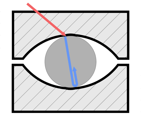
Transmission Path Evasion Example 1: Small Indentation

The red sound wave of a vibration enters the bearing at the point of contact along the indentation. The blue sound wave begins traversing across the diameter of the bearing. Upon reaching the end, some energy reflects back to the point of entry.

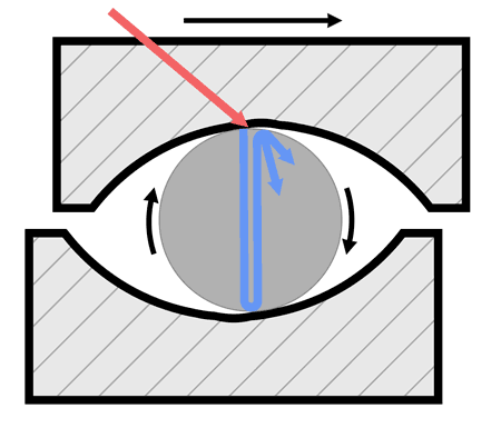
After a short period of time, the upper raceway has displaced in response to the vibration, rotating the bearing in the process. The bearing is now rolling up the inclines of the raceways such that the original point of entry for the sound wave is no longer in contact with the raceway. Without a path for the blue sound wave to exit back into the raceway, it reflects within the bearing until it is dissipated as heat.

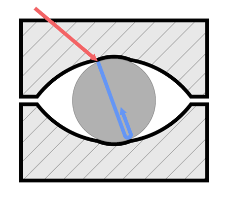
Transmission Path Evasion Example 2: Large Indentation

Similar to example 1 above, the red sound wave enters the bearing at the point of contact with the indentation. The blue sound wave propagates across the bearing and reflects back again.

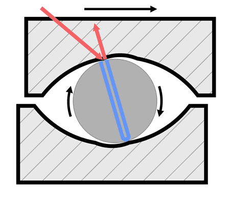
The large indentation is still in contact with the point of entry by the time that the blue sound wave has reflected back. The reflected sound wave is therefore able to pass back into the raceway through the same point of entry.

Factors Influencing Transmission Path Evasion

Below are 4 factors which influence the transmission path evasion ability of a ball bearing rolling in a curved raceway. Under each factor we describe the design elements we incorporated in the new 3rd isolation stage in our Carbide Base Diamond footer.

Pendulum Period

A bearing rolling in a curved raceway will act like a nonlinear pendulum. The equivalent pendulum length is related to the difference of the radius of the curvature of the raceway to the radius of the bearing. The larger the difference, the longer the pendulum’s length and therefore period. When the pendulum’s period is long and the indentation is small, a relatively small amount of time is spent with the bearing in contact with the indentation.


We designed our bearing raceways to have a large radius of curvature relative to the bearing diameter to achieve a long pendulum period. This is ideal since it reduces the relative time in which reflected sound waves have a chance to escape the bearing through the entry point along the indentation. It also lowers the natural frequency of the isolator to improve isolation of low frequencies.

Sound Velocity in the Bearing

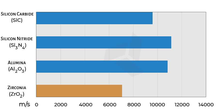
The velocity of sound in the bearing material will affect the time that it takes for a sound wave to traverse across the bearing and then return back to the point of entry. A material with low sound velocity is ideal since the sound wave will take longer to travel back to the entry point. This allows more time for the bearing to rotate past the indentation before the sound wave returns to the entry point.


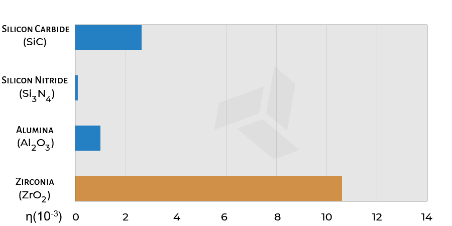
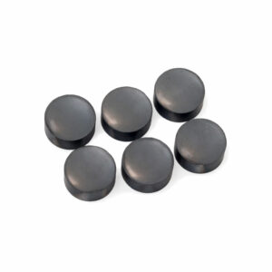
Of the ceramics commonly used for ball bearings, zirconia stands out for its low longitudinal sound velocity. Zirconia also has better vibration damping properties than many other ceramics[2]. It is for these reasons in addition to a high toughness that zirconia bearings are utilized throughout our Carbide Base footer.

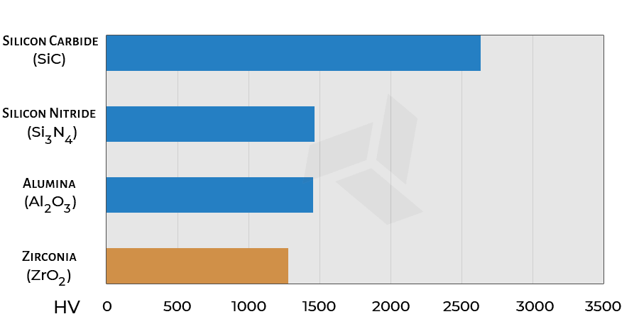
Hardness
Sound Velocity
Maximum Damping
Bearing Diameter

The bearing diameter dictates the distance that the sound wave must travel within the bearing. A large diameter is ideal since it increases the distance and therefore time that the sound wave must travel before returning to the entry point.


The bearings utilized in the new 3rd isolation stage of the Carbide Base Diamond footer have a relatively large diameter – the largest that would fit in the housing. Any larger and the raceway must be made so shallow that it can have issues keeping the bearing reliably centered.

Raceway Hardness

A bearing raceway with a high hardness is ideal since it will better resist deformation caused by contact with the bearing.

To achieve a high hardness, the bearing raceways in the 3rd isolation stage of our Carbide Base Diamond footer are machined out of solid ceramic using diamond tools. After machining, the raceways undergo a polishing process to achieve a smooth surface finish. The thorough polishing is to minimize surface imperfections which could impede the ability for the ball bearing to roll in response to small amplitude vibrations.


After polishing, the bearing races are coated with amorphous diamond using a Physical Vapor Deposition (PVD) process. This outer layer has an extreme hardness of up to 6500 HV. PVD diamond also has a low coefficient of friction of about 0.10 or about 1/10th that of polished steel. This further reduces the rolling resistance of the bearings within their raceways.

Measuring Bearing Raceway Indentation

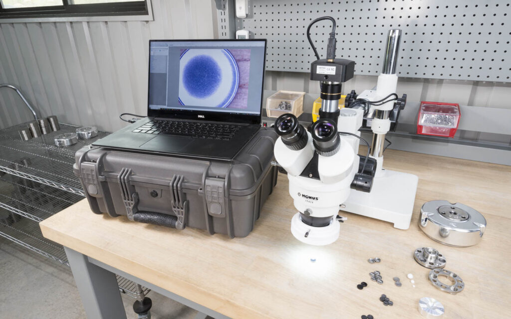
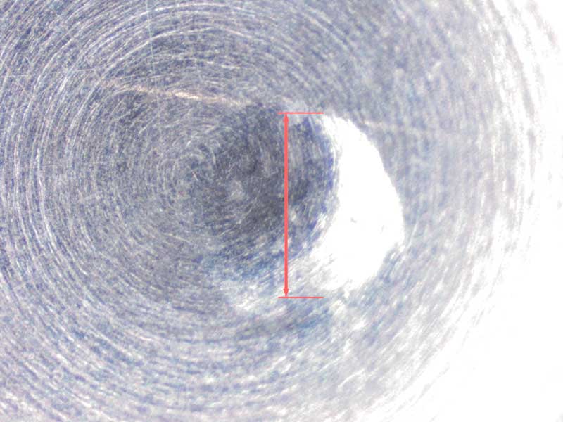
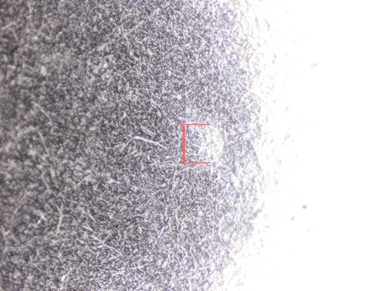
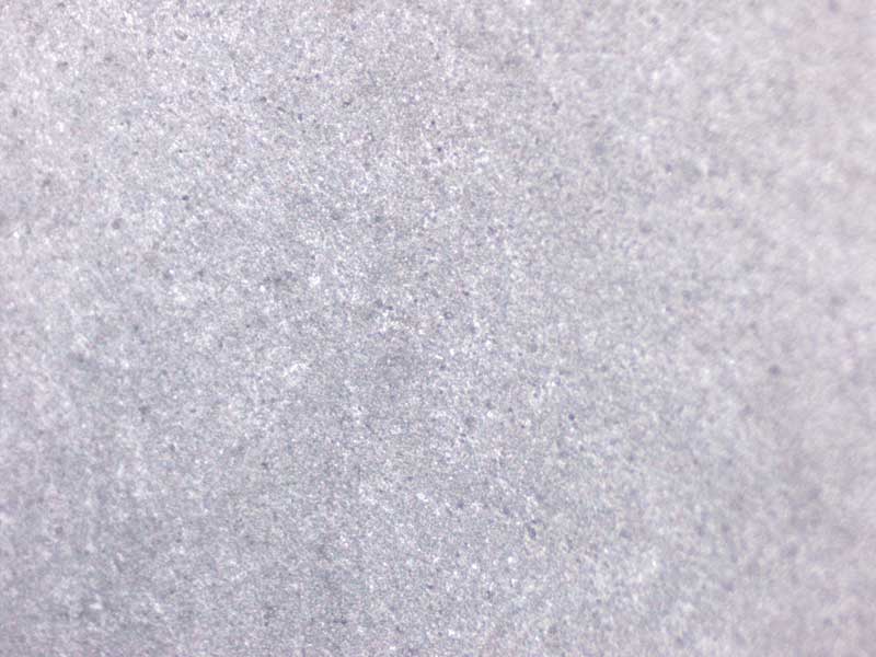
An experiment was conducted to analyze the indentation of bearing raceways caused by a ball bearing. A 90 kg (200 lbs.) weight was applied on top of a 4 mm diameter zirconia bearing sitting in raceways with similar curvatures made of 7075 T6 aluminum, 1095 hardened steel, and the PVD diamond coated ceramic from our Carbide Base Diamond footer. A microscope was then used to measure the diameter of the indentation on the raceway surfaces of the various materials.

Material

7075 T6 Aluminum

Surface Hardness

180 HV

Indentation Diameter

875 μm

Material

1095 Hardened Steel

Surface Hardness

830 HV

Indentation Diameter

254 μm

Material

PVD Diamond Coated Ceramic

Surface Hardness

Up to 6500 HV

Indentation Diameter

Not detectable at 20x magnification

Vibration Isolation Measurements

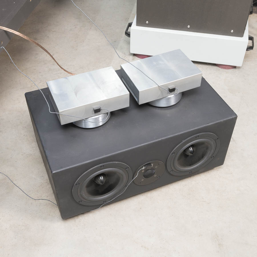
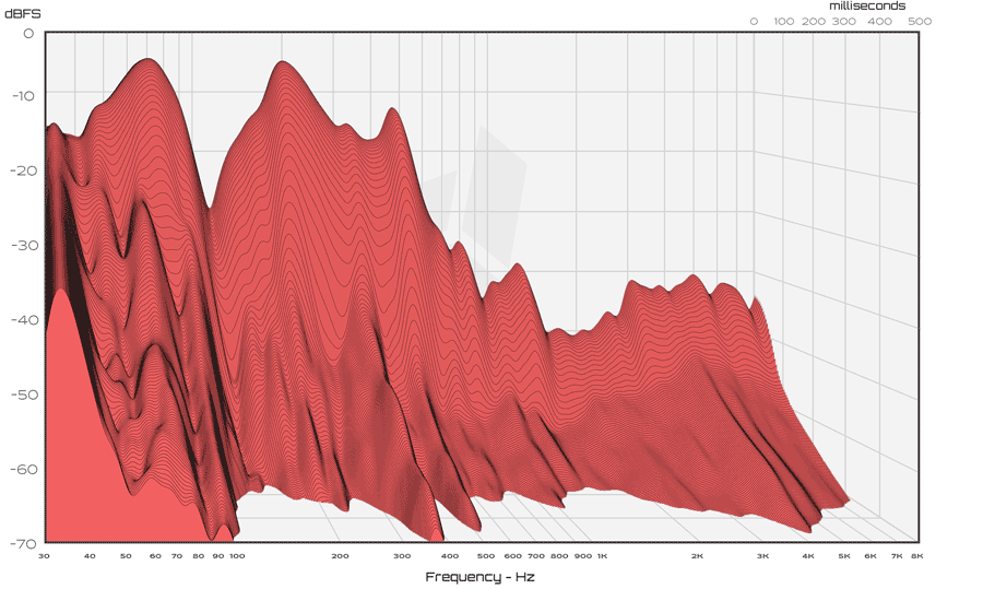
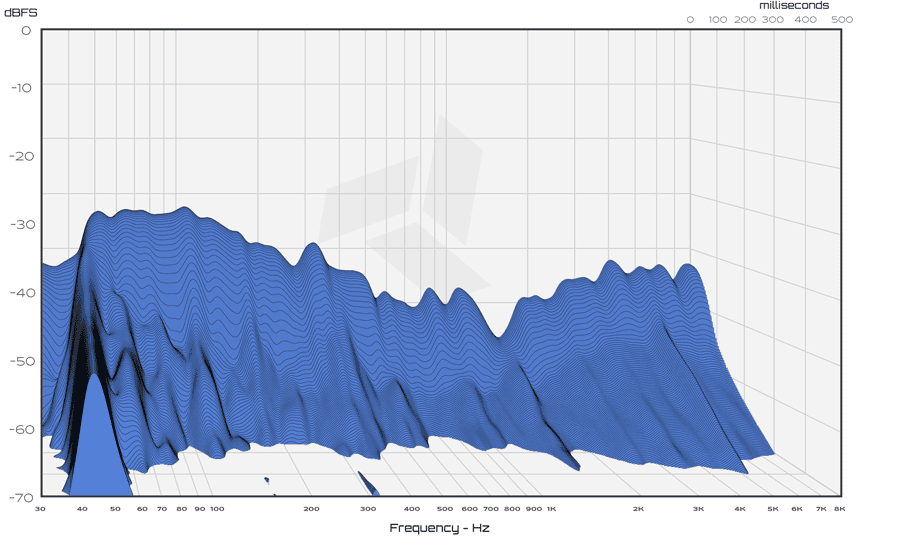
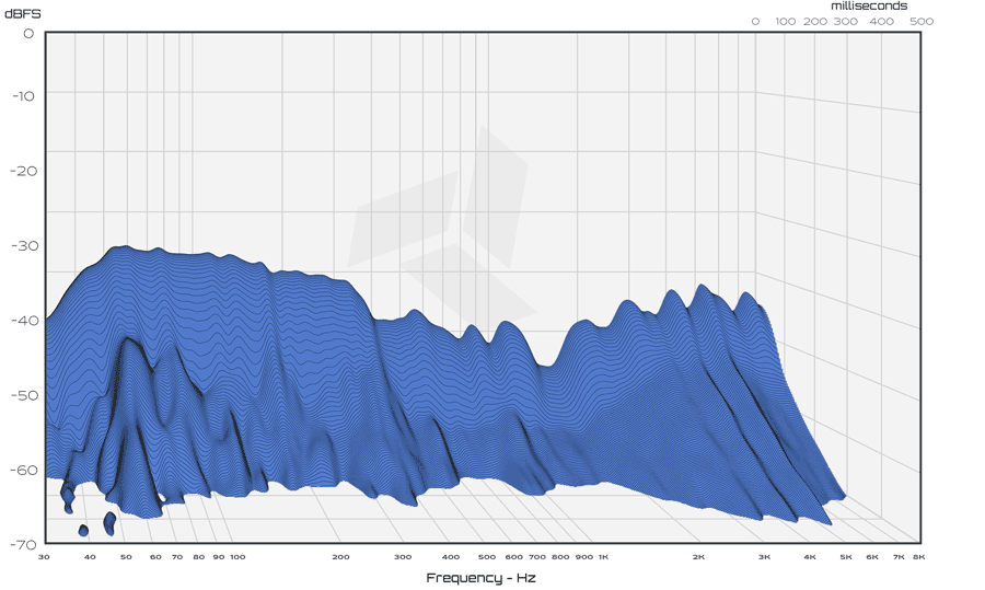
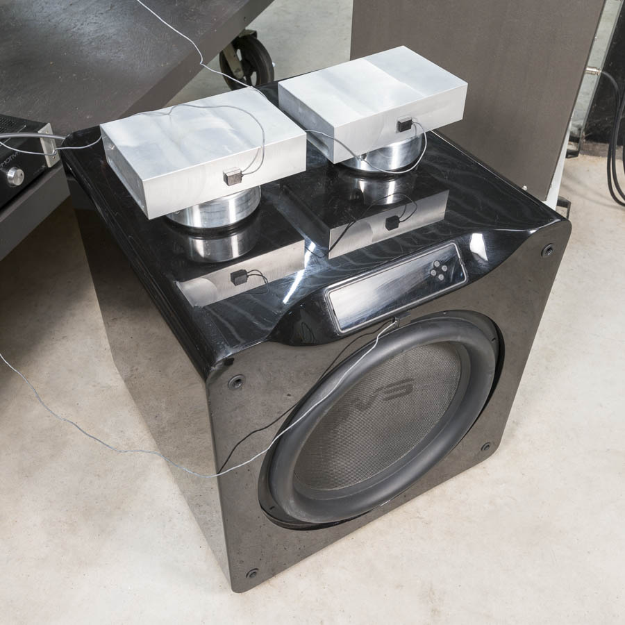
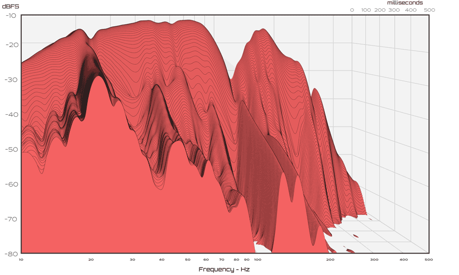
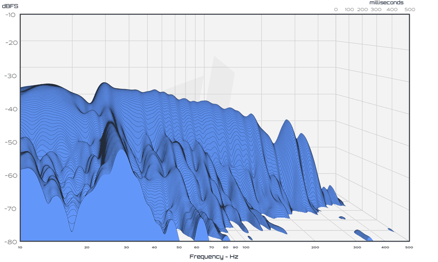
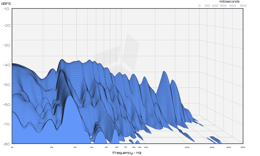
The following measurements were taken using a process similar to our Survey of Audio Footer Designs. A 2-way loudspeaker and a subwoofer were placed on a concrete floor. Separate 3.6 kg (8 lbs.) payloads were placed on top of 3 Spikes, a Carbide Base footer, and a Carbide Base Diamond footer. The Super Light ViscoRing™ was installed in both footers. Log swept sine signals were then played through the loudspeaker and subwoofer. Accelerometer sensors attached to the payloads were used to measure the horizontal vibrations passing through the devices.

Loudspeaker Measurements

Log swept sine excitation from 30 Hz to 8 kHz. Horizontal vibrations measured with 20 dB gain using an ACH-01 accelerometer sensor.

Spikes
Carbide Base
Carbide Base Diamond

Subwoofer Measurements

Log swept sine excitation from 10 Hz to 500 Hz. Horizontal vibrations measured without gain using an ACH-01 accelerometer sensor.

Spikes
Carbide Base
Carbide Base Diamond

Conclusion

The vibration isolation performance of our Carbide Base Diamond footer demonstrated a marked improvement with the addition of the new 3rd isolation stage. By designing with transmission path evasion in mind we were able to achieve a higher level of vibration isolation and dissipation. The vibration amplitude and decay was measurably better despite the already high performance level of the standard Carbide Base footer. The improvement was across all audible frequencies but most significant in the bass region.

References

[1] Kemeny, Zoltan A. “Mechanical signal filter.” US 6520283 B2, United States Patent and Trademark Office, 18 February 2003. Google Patents, https://patents.google.com/patent/US6520283B2


[2] Zhang, J., Perez, R. J., and Lavernia, E. J., “Documentation of damping capacity of metallic, ceramic and metal-matrix composite materials”, Journal of Materials Science, vol. 28, no. 9, pp. 2395–2404, 1993. doi:10.1007/BF01151671