Utilizing Low Shape Factor Elastomers
Viscoelastic polymers or elastomers are widely used in vibration control applications due to their high damping capability. Elastomers can also effectively isolate low frequency vibrations by being formed in certain shapes. Shape factor is the term of art used to quantify the isolation performance of a given elastomer shape. The implication is that the lower the shape factor, the lower the potential resonance frequency. A low resonance frequency typically results in a wide bandwidth of vibration isolation. This is due to the isolation of vibration frequencies above the resonance frequency.
For most common shapes, shape factor is generally defined as:
The average loaded surface area is the average of the upper and lower surface areas supporting the payload. The bulging surface area is the surface area free to bulge perpendicularly to the load.
The stability of an elastomer can become compromised below a certain shape factor as the material becomes increasingly tall and narrow. Some elastomer manufacturers recommend staying above a shape factor of 0.3 in order to prevent buckling – an issue that can cause the supported equipment to topple over.
When designing the ViscoRing™ elastomer utilized in the Carbide Base footers, a shape factor of 0.17 was planned. This was chosen in order to push the resonance frequency low enough so that the lowest audible frequencies could be effectively isolated.
Improving Stability
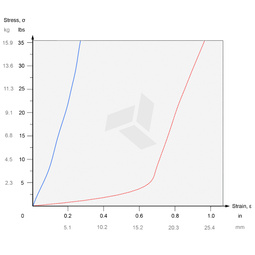
An experiment was conducted to test the ability of the ViscoRing™ to vertically support a load and avoid buckling. The experiment consisted of gradually applying weight and measuring the vertical deformation of the material. Weights were applied on top of the Medium ViscoRing™ in 1.13 kg (2.5 lbs) increments in a room temperature environment. The vertical deformation distance was plotted in the form of the stress-strain curve shown. The y-axis represents the stress or weight applied, and the x-axis represents the strain or vertical deformation caused by the application of weight.
The red curve shows the ViscoRing™ alone without a housing. It can be seen that shortly after the initial application of weight, the material began to buckle and deform considerably under the load. The material did a poor job of supporting even a small mass which was expected given the extremely low shape factor.
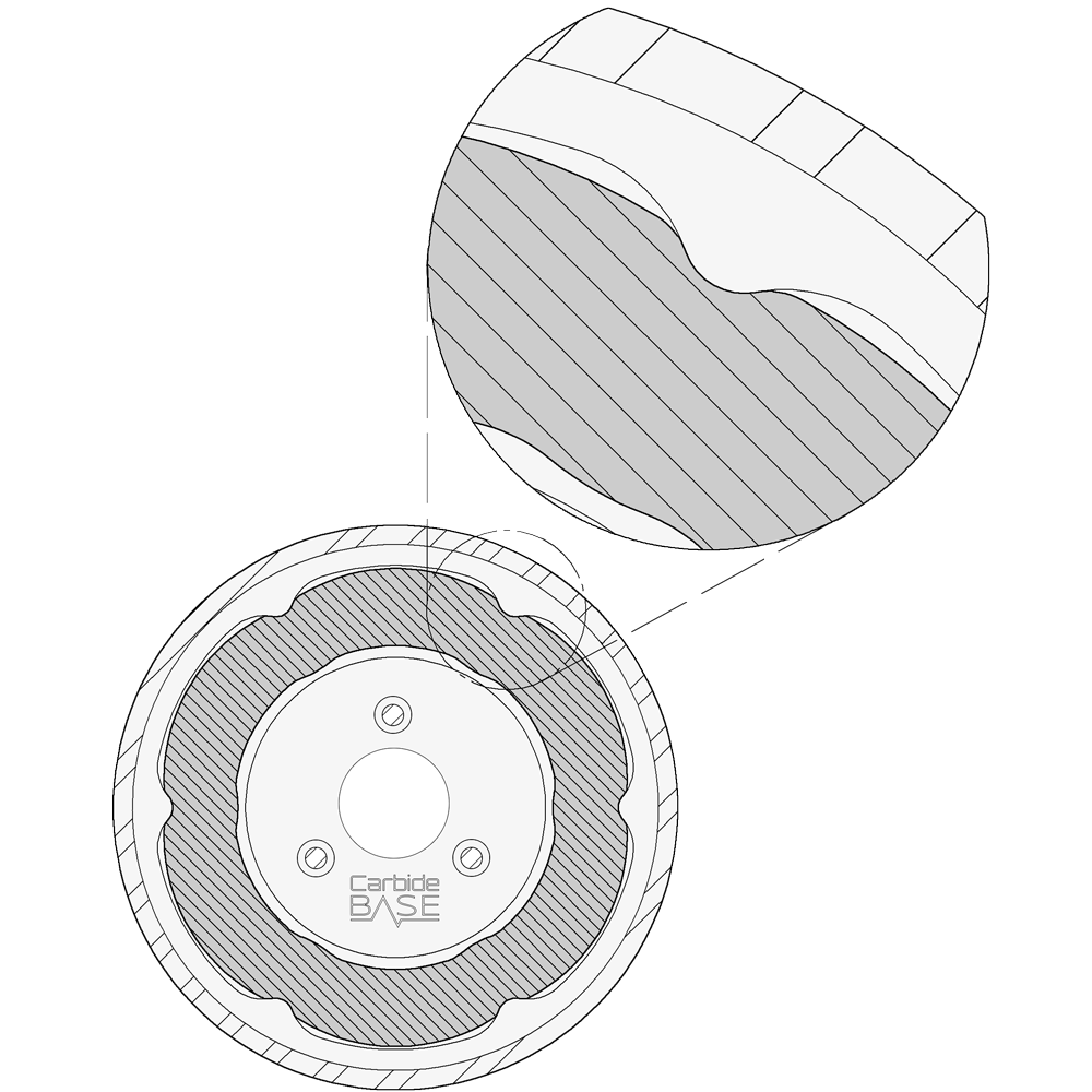
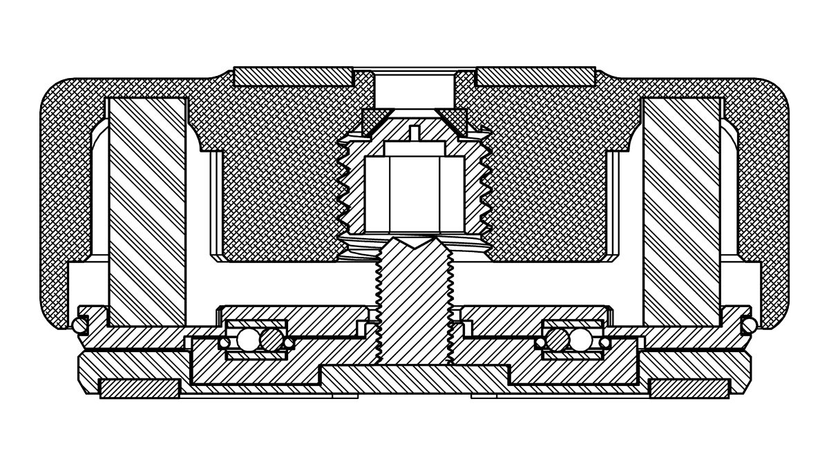
To improve the stability of the ViscoRing™, a housing was designed for it within the upper portion of the Carbide Base footer as shown in the above simplified graphic. Ridges were added at spaced intervals around the perimeter of the ViscoRing™ to brace it and prevent buckling. The ridges were spaced apart at varying distances from the outside of the ViscoRing™. This freed a substantial surface area to bulge outward thus preserving much of the performance benefit of the low shape factor.
As the ViscoRing™ bulged outward, a progressively larger percentage of the bulging surface area came into contact with the sloped ridges. This increase in shape factor with an increase in payload mass gave a more consistent resonance frequency across a broader range of payload masses. In other words, isolation performance of the Carbide Base footer became more constant across varying payload weights with this progressive shape factor design.
The blue curve shows the same ViscoRing™ placed in the housing of the upper portion of the Carbide Base footer. A relatively linear increase in vertical deformation with an application of weight was observed. The material was not buckling as intended. The stiffness of the material eventually beings to gradually increase with increased stress as more of the unloaded surface area is braced. This desirably increased the maximum weight supporting ability of the material.
Elastomers are unable to be compressed into a smaller volume. Therefore, elastomers must be allowed to bulge outward in order to deform under a load. The selectively braced ViscoRing™ did not show a sudden increase in slope or stiffness as would have occurred if the material was prevented from further bulging. A low stiffness or spring rate is important in achieving a low resonance frequency with a spring-mass system such as this.
Improving Horizontal Isolation
Once successful in utilizing a low shape factor elastomer for vertical isolation, similar benefits for horizontal isolation were desired. Horizontally oriented low shape factor elastomers along with ball bearings were incorporated to further improve horizontal isolation performance.
Utilizing ball bearings to provide horizontal isolation is a well known concept. Many designs interpose ball bearings between curved bearing raceways[1].
The design devised for the lower portion of Carbide Base footers was different with the bearing raceways being flat rather than curved. The horizontally oriented elastomers acted as highly damped springs keeping the device centered in response to vibrations. In order to minimize deformation and rolling resistance, zirconia was chosen for the bearings and polished hardened spring steel for the bearing raceways.
Graphing Horizontal Isolation
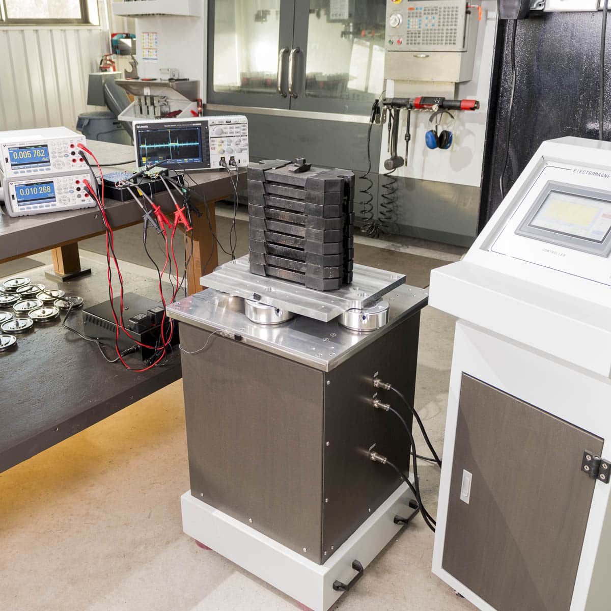
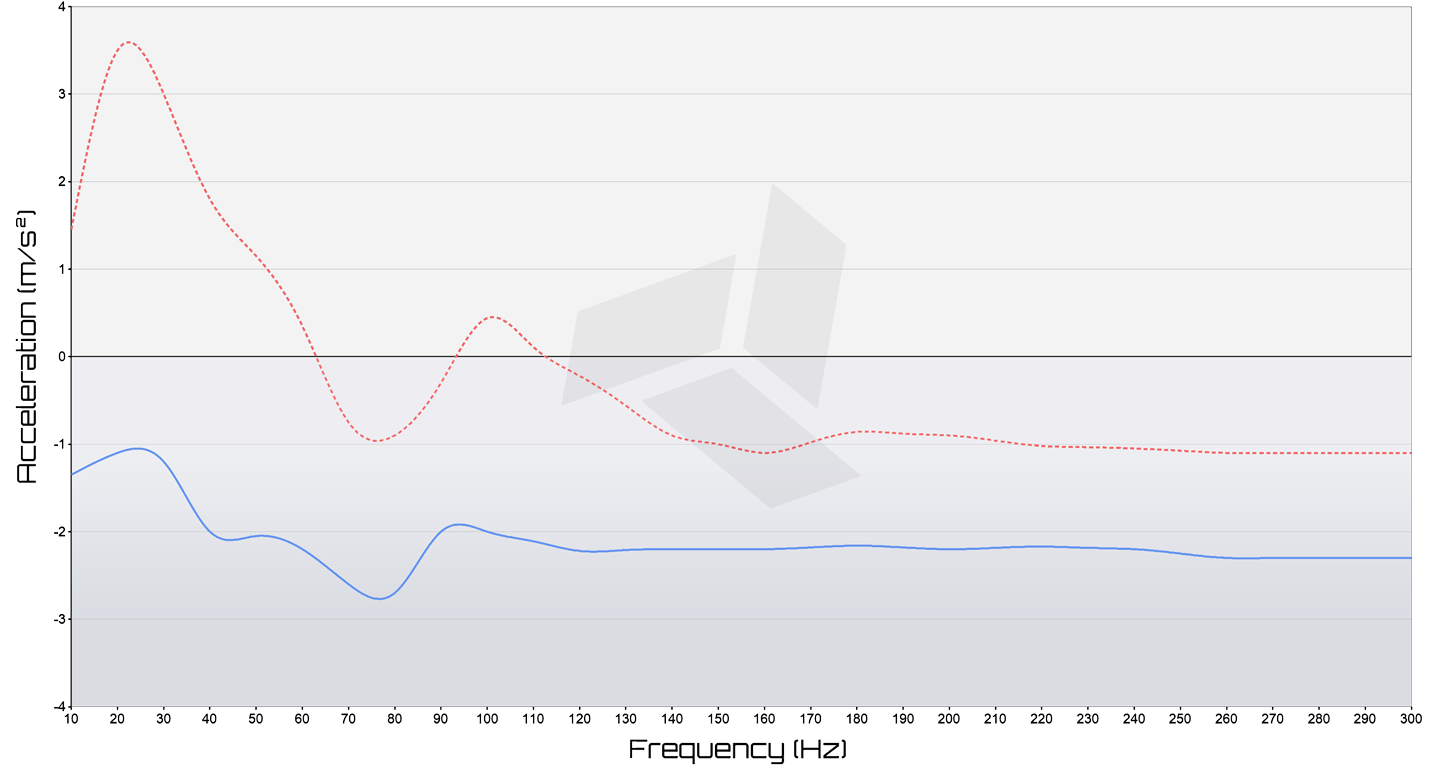
The forward and back (Y axis) vibration frequency was set in 10 Hz increments from 10 Hz to 300 Hz. The voltage output of both sensors were plotted at each interval. The amplitude of the table was adjusted to ensure that the table was oscillating sinusoidally with an acceleration of approximately 4 m/s2.
Subtracting the output of the sensors yielded the transmission of vibrations through the Carbide Base footers. Positive values indicated an amplification of vibrations through the device. This was expected at vibration frequencies around the resonance frequency of the device. Negative values indicated a reduction in vibrations generated by the table. In other words, an isolation of vibrations which was desired. The more negative the value, the greater the isolation.
The red line shows measurements taken with the Carbide Base footers missing the ball bearings and horizontally oriented elastomers. Only the ViscoRing™ elastomer was providing isolation. The blue line shows measurements taken with the bearings and horizontal elastomers in place. The incorporation of ball bearings and horizontal elastomers substantially improved the horizontal isolation performance. The reduction in vibration amplitude was particularly pronounced around the resonance frequency indicating a higher level of damping.
Conclusion
Several design features were incorporated into the Carbide Base footers to reliably utilize low shape factor elastomers for vibration isolation. Elastomers formed in shape factors that were previously considered too unstable were made sufficiently stable with a specially designed housing. The additional combination of bearings and horizontally oriented elastomers further improved horizontal isolation. These novel features were later incorporated into a pending patent.


